TRH-100 Calibration Information
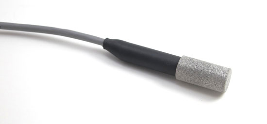
TRH-100 Temperature & RH Probe
The following information is provided for customers interested in calibrating the TRH-100 Probe with their own humidity calibration equipment. Note that the TRH-100 Probe has a very low drift spec of less than 1% RH in 5 years.
The TRH-100 Probe requires 5 vdc excitation at 2 ma max.
Warm-up time (the time from when 5 vdc power is applied until the humidity output signal is stable) is 100 ms.
The probe has four 24 awg insulated leads.
TRH-100 Lead Functions
| Black | Signal return (ground) |
| White | 5 vdc power |
| Green | Humidity output signal |
| Red (or Yellow) | 30k ohm Thermistor |
CAUTION! The TRH-100 Probe's power lead is not reverse polarity protected. Pace Data Logger's provide current limited power to the TRH-100. If the probe will not be used with a Pace Data Logger, carefully check your connections before applying power.
RH Output Signal
The Humidity output is a linear dc signal ranging from approximately 0.9 Vdc at 0% RH to 3.9 Vdc at 100% RH. Each TRH-100 probe ships with scaling values typed on a label bonded to the probe's cable.
XR450 Scaling Values: The "Low" scaling value is a negative value and represents the equivalent % RH at 0v. The "High" scaling value represents the equivalent % RH at 5 V. Both of these values are outside the 0 to100 (% RH) range of the TRH-100 because the RH output signal ranges from approximately 0.9 to 3.9 Vdc.
XR5 Scaling Values: Separate Slope / Offset scaling values are listed for the XR5-SE. Using the Slope / Offset values, the RH reading is calculated by multiplying the RH output signal voltage by the Slope, and then adding the Offset to the result.
Recalibration
Recalibration should be performed only if required, typically after a long interval (years) of use.
In order to perform a recalibration of the TRH-100, the probe must be placed in an environment (humidity chamber) with a precisely known humidity and stable temperature near 25°C. Record the output voltage of the TRH-100 at a precise, stable low RH environment, and at a precise, stable high RH environment (to read the RH signal as a voltage, see Note below). For example, read the TRH-100's output voltage at 20% RH and 70% RH. Then using these two Voltage vs %RH readings apply the following formulas:
Y2 = High %RH value
X2 = voltage output at High %RH
Y1 = Low %RH value
X1 = voltage output at Low %RH
Slope = (Y2 - Y1) / (X2 - X1)
Offset = Y1 - (Slope * X1)
The calculated Slope and Offset terms can be used with the XR5-SE. To convert to the Low / High scaling used by the XR450, use the following formula:
Low scaling value = Offset
High scaling value = (5 * Slope) + Offset
Example:
At 20% RH, TRH-100 output voltage reads 1.5v
At 70% RH, TRH-100 output voltage reads 3.1v
Slope = (70 - 20)/(3.1 - 1.5) = 31.25
Offset = 20 - (31.25 * 1.5) = -26.875
Use the calculated Slope and Offset for the XR5-SE. For the XR450:
Low Scaling value = Offset = -26.875
High Scaling value = (5 * Slope) + Offset = (5 * 31.25) + -26.875 = 129.37
Note: To read the RH output signal as a voltage:
XR450: Change the XR450's scaling for the RH channel to Low value = 0, High value = 5. Set Type on only One channel (any channel) to "Temp/RH"
XR5-SE: Change the XR5-SE's scaling for the RH channel to Type: "0 - 5V", Slope = 1, Offset = 0. Set "Sensor Excitation" (Main tab) to 150 ms.
Note: All references to the XR450 Data Logger apply to the XR440 Data Logger.
XR450 Data Logger (4 channels)
XR5-SE Data Logger (8 channels)