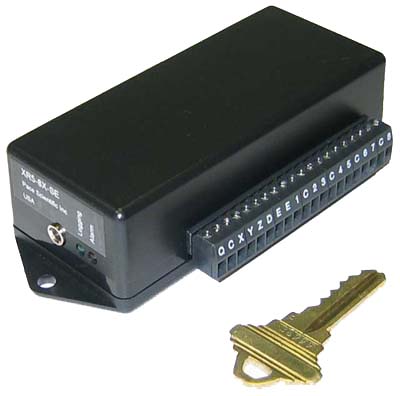
XR5-SE Data Logger
Specifications
Note: Specifications are also listed in the XR5-SE User's Guide
Overall dimensions: 4.88” length, 2.21” width, 1.28” height. (124mm x 56.2mm x 32.5mm). Length includes mounting ears, width includes detachable terminal block.
Weight (with batteries): 4.2 ounces; 120 grams
Mounting: Two 0.187” dia. mounting holes on enclosure centerline, spaced 4.5” (114.3mm) apart.
Input termination: Detachable 20 position screw terminal block.
Screw terminals: 20
Recommended Screw Terminal Wire Size: 16 to 28 awg, solid or stranded. Use stranded wire if multiple wires are terminated in a single terminal block.
Operating limits: -40 to 78°C (-40 to 172°F); 5-90% R.H. non-condensing
Altitude: No limitations, the XR5 is suitable for use in a vacuum environment.
Case material: Tough, flame retardant ABS plastic; Flammability rating UL 94V-O
IP Protection rating: IP50
Analog Inputs
Resolution: 12 bits (1 part in 4096, 0.024% F.S.)
Temperature Resolution: 0.02°C at 25°C (12 bits); 0.06°C or better from -25 to 75°C
Temperature Accuracy:
± 0.15°C from 10 to 40°C; ± 0.3°C from -25 to 85°C
Temperature accuracy is valid over the full operating
temperature range of the XR5 Data Logger (-40 to 78°C) and assumes use of Pace
PT9xx series Temperature Probes.
Vdc Ranges: 0-5 V and 0-2.5 V
Either range is selectable for each analog channel (1-8).
Accuracy, 0-2.5 V range: ± 0.15% F.S. (10-40°C); ± 0.20% F.S. (0-60°C)
Accuracy, 0-5 V range: ± 0.35% F.S. (10-40°C); ± 0.40% F.S. (0-60°C)
Repeatability: ± 0.05% F.S. for <10°C ambient temperature change.
Input impedance: >10Mohm (for all logging modes and when inactive or not logging).
Resistance Range
(Two wire resistance)
Resistance range is selectable for each analog channel (1-8).
Resolution at 30k ohms: Better than 0.1% of reading (2 wire resistance).
Accuracy at 30k ohms: ±0.15% of reading.
Useable range: Approx. 100 ohms to 1.5 Mohms (measurements near 30k midpoint have highest
resolution).
Potentiometers
A potentiometer can be read by connecting its wiper to an analog input, selecting the 0-2.5 Vdc range and connecting the other leads to terminals C and D. Wired in this way, a potentiometer from 500 ohms (or lower) to 100k ohms (or higher) can be used. Power draw from the D terminal will be about 5 ma for a 500 ohm potentiometer, and about 0.025 ma for a 100k potentiometer. In either case, potentiometer resolution would be 1 part in 4096 or 0.024%.
Optional Millivolt Ranges
Accuracy, "Half-Range" selected: ± 0.45% F.S. (10-40°C); ± 0.50% F.S. (0-60°C)
Accuracy, "Full-Range" selected: ± 0.65% F.S. (10-40°C); ± 0.70% F.S. (0-60°C)
Input impedance: >10Mohm (for all range selections and logging modes and when inactive or not logging).
Input offset: 5uV max. at 25°C, 10uV max. from -40 to 60°C.
Offset voltage drift: 0.02uV/°C max.
Millivolt resolution: See XR5 Data Logger Millivolt Range Table.
Thermocouple accuracy: See tables in XR5-SE User's Guide starting on page 97.
Pulse Inputs
Three Pulse inputs (X, Y and Z) accept voltage pulses or unpowered contact closures. Alternate functions: Ch X: External Trigger, Ch Y: Peak Count (2 second window), Ch Z: Alarm Output.
Pulse Inputs are disabled if Fast Logging is active (2Hz to 1000Hz) see page 33 of XR5-SE User's Guide for details.
| Pulse Type (selected in setup) | Maximum Rate | Minimum Hold Time | Debounce Time |
|---|---|---|---|
| Mechanical Switch | 15 Hz | 30 ms | 30 ms |
| Solid State Switch | 900 Hz | 0.5 ms | 0.5 ms |
Maximum count per Log Interval: 16,777,215
Active edge: Falling edge
Input Type: Schmitt Trigger
Dry contact: Bias voltage from XR5: 3.3 V
Current when contact is closed: 3.3 microamps
Voltage Pulse
Positive range: 2.3 to 18 V
Negative range: -18 to 0.8 V
Alarm Output (select on Ch Z): 0.25 V inactive, 1.8 V active (with 100k resistor from C to Z)
Input Protection
Analog and pulse inputs meet the following surge protection requirements:
IEC 61000-4-2 (ESD) 15 kV (air) 8 kV (contact)
IEC 61000-4-4 (EFT) 40 Amps (5/50ns)
Continuous Fault Voltage (maximum):
Pulse inputs (channels X, Y, Z): ± 24 Vdc
Analog inputs (channel 1-8): ± 24 Vdc *
* Analog input (channel 1-8) fault voltage is any voltage above 5.6 V or below -0.25 V (with respect to the C terminal). A fault voltage within ± 24vdc on one or more analog inputs will not damage the XR5, but may saturate the input multiplexer and cause erroneous readings on all analog channels.
General Specifications
Communication interface: Serial, 3 wire, EIA/TIA-562 signal levels (RS232 compatible), 9600 bps. (8 data bits, 1 stop bit, no parity, no flow control)
LED indicators: 2
Green:
Blink every 5 secs: Slow logging active.
Blink every 1 second (or faster): Fast logging active.
Red:
Blink every 5 secs: One or more active Alarms.
If external power is applied to the Q terminal, the Red LED stays ON steady when an Alarm is active.
The Red LED does not function when Fast Logging is active.
Number of channels: 11 or 12
(8 analog input
channels, 3 pulse input channels; Millivolt option adds ambient temperature
channel)
Logging modes: Manual, Pre-set, Log on Alarm, Cycle Logging (start time, active period, pause period, stop time), Log on Ext. Trigger, Manual/Wrap, Preset/Wrap.
Manual (slow), Log on Alarm, Log on External Trigger and Cycle Logging may have any number of individual data segments, limited only by available memory.
Log on Ext. Trigger (Slow) includes a selectable Stop Delay time that causes logging to continue after a Stop trigger occurs, for the duration of the selected Stop Delay time.
Sampling modes: Standard, Average (1 second internal sampling), Peak (1 second internal sampling), Differential (Ch1-Ch2, Ch3-Ch4, Ch5-Ch6, Ch7-Ch8).
Peak and Average sampling are only available when using the following Slow Logging modes: Manual, Preset, Manual/Wrap Preset/Wrap and Cycle.
Memory capacity:
XR5-SE: 127,284 bytes (up to 63,642 analog readings)
XR5-SE–M: 520,400 bytes (up to 260,200 analog readings)
Each analog reading consumes 2 bytes. Each pulse reading consumes 4 bytes. The start of each data set consumes 12 bytes. Log modes Manual/wrap, Preset, and Preset/wrap have a single data set. Other logging modes (Manual, Log on Alarms, Log on Ext. Trigger, Cycle Logging) may have many data sets.
LogXR Software displays the Total Log Time on the Main tab of the Setup screen based on the current Setup.
Data retention: Logged data and Setup data: Over 100 years with no power.
Logging interval: Any time interval from 1 second to 24 hours, plus 2 Hz to 1000 Hz for Fast Logging modes. During Fast Logging, Real Time display and data transfers are not available and pulse count inputs are disabled.
Fast Logging above 100 Hz results in reduced channel count (see page 34 of the XR5-SE User's Guide for details).
Alarming capabilities: All eight analog channels have individually adjustable high and low alarm limits. Configurable alarm responses for all slow logging modes include activate Alarm output, dial out to a host computer (modem required), send a descriptive SMS alarm message to a cell phone (GSM modem required).
Alarms are disabled for all fast logging modes except ‘Log on Alarm’.
Real Time display: Displays current readings and alarm conditions of all active channels. Updated every 2 seconds or when readings are logged to XR5 memory (selectable). Can be active while any slow logging mode is active with no effect on the logging session.
Real Time write to file: Logs real time data to a text file every 2 seconds or when readings are logged to XR5 memory (selectable). When active, Real Time display is also active. Can be active while any slow logging mode is active with no effect on the logging session.
Data transfer: Binary Xmodem transfer, converted to readable text file. Data may be transferred while any Slow Logging mode is active with no effect on the logging session. All data is transferred at 9600 bps.
Clock accuracy: ± 1 minute per month at 25°C; ± 2.5 minutes per month from -10 to 60°C.
Clock accuracy is also Time Stamp accuracy for all logging modes and logging intervals.
Battery life: Dependent on logging rate, channel Type (Standard, Average, or Peak), Real Time Mode use, data transfers, selected excitation time, and the power drawn from the D and E terminals to power external sensors.
LogXR Software displays the "Estimated battery life" on the Main tab based on the current setup and the Estimated Sensor milliamps (if any). See pages 29 and 30 of the XR5-SE User's Guide for details.
Battery type: Lithium, AA size, 3.6 volt; 2 required (Tadiran TL-5903/S or equiv.)
External power input: Voltage range: 8.0 – 14.0 vdc (9vdc or 12vdc Regulated Supply)
Warning: A voltage higher than 14 Vdc on the External Power Input may damage the unit.
Power Consumption: Average current for slow logging intervals is approximately 30 microamps (0.030 milliamps) plus periodic excitation current (if any) from the D and E terminals.
Excitation terminals:
E: 5 Vdc; maximum current: 30 ma (current limited).
D: 2.5 Vdc; recommended maximum current: 40 ma.
Power from the excitation terminals is pulsed for the duration of the selected Excitation Time, just prior to logging readings or reading Real Time data. If Fast Logging (2 Hz – 1000 Hz), excitation terminals are continuously powered ON for the duration of the Logging Session.
Sensor Excitation Time: User selectable for any of the following times: 30 ms, 150 ms, 1 second, 5 seconds, 10 seconds.
Specifications subject to change without notice.